Digital audio 17
Digital audio synchronisation
- Video
- Script
Welcome to this tutorial on digital audio synchronisation.
Digital audio synchronisation is essential when audio devices are connected digitally. Unlike analogue audio connections, when digital audio signals travel between devices (such as a DAW and and external hardware effect processor) they must be synchronised by a common clock. Like cogs in a mechanical system, they must mesh.
Devices that we regularly need to connect include ..
- DAWs
- digital audio interfaces
- stand alone analogue to digital audio converters
- digital mixers
- CD players
- pre-amp channels with a digital outputs
- effects processors
In this context we are not talking about audio signals travelling down computer connectors such as USB, FireWire, or ethernet leads. Signals in those situations can usually be considered to be synchronised within an integrated computer environment.
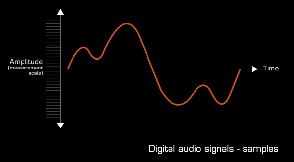
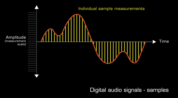
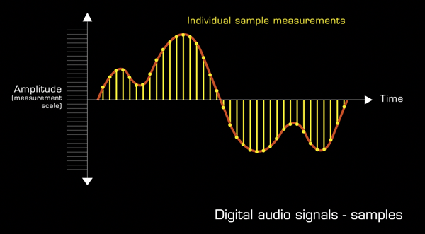
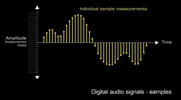
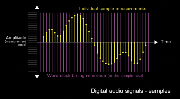
Caption - Digital audio signals
Digital audio signals consist of long sequences of individually discreet measurements of amplitude (called samples) taken at very precise intervals. They are like super precise join-the-dot pictures. The number of samples per second is expressed as the signals sample rate or frequency. For example, there are 48,000 samples of amplitude every second in a 48KHz digital audio signal.
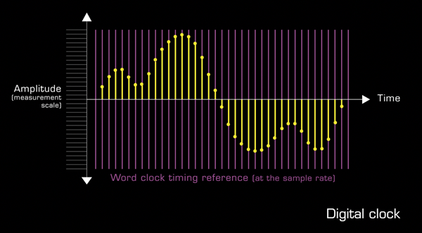
Caption - Digital clock
Digital audio devices require a super accurate clock to ensure the precise timing of samples. If they are operating alone, they use their internal clock. But in a network of connected devices, timing errors can occur, which at best cause subtle audible distortion, and at worst produce audible clicks and pops and even complete drop-outs.
Caption - Digital clock master
It is therefore essential that individual devices in a digital audio network, conform to a common timing clock, known as the clock master. The clock master is set to a sample rate which all connected devices must follow.
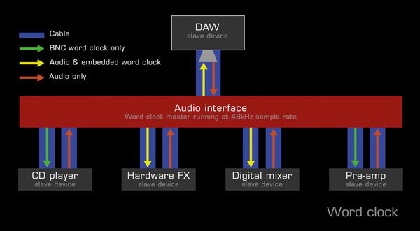
Caption - Word clock
Work clock is a timing signal passed between devices on a digital audio network. One device is set as the clock master and it's job is to generate and send a word clock signal to the other devices on the network, each of which are set to slave to it. This ensures that the timing of all devices is synchronised. Word clock is embedded in almost all digital signals or can be sent as a separate signal commonly referred to by the connector it uses, BNC. The word clock signal embedded in an AES3 signal is also known as AES11.
Caption - Timing errors
When an analogue signal is converted into a digital signal by an analogue to digital converter synchronised by its own internal clock, the samples occur at very precise intervals. Almost all modern converters (last 10 years) are super accurate. However, once converted there are 3 primary conditions that can produce timing errors.
They are ..
- Jitter
- Drift
- Lack of sync
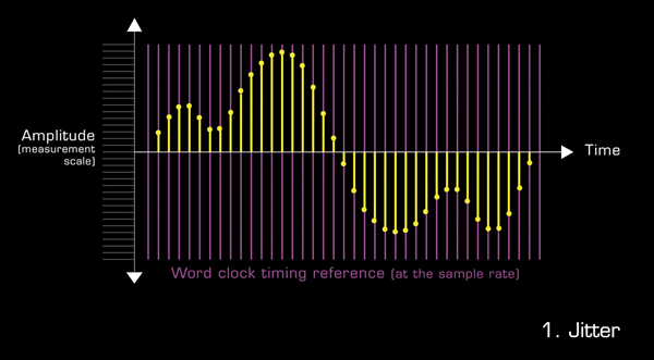
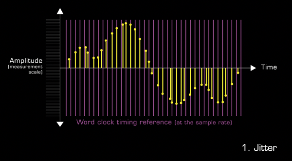
Caption - 1. Jitter
Jitter is sample timing irregularities in an individual digital signal and is most commonly caused by the interference issues and electrical properties of AES, SPDIF and BNC leads as a digital signal travels between devices. The longer the lead is, the worst the jitter can become. Jitter is a problem for larger networks carrying signals long distances, but not usually a big problem in smaller project and home studios.
Jitter can also be produced by a digital device, such as a converter or effect processor, but new super accurate chips commonly used in modern audio devices have minimised it.
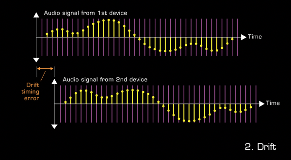
Caption - 2. Drift
Drift is caused by serious transmission problems in a lead or by the clocks of two devices in a network operating out of sync with each other. This can happen if the devices are not adequately synchronised, or one clock is operating less precisely than the other.
Caption - 3. Lack of sync
In this situation, devices in a network are operating independently according to their own internal clocks and are not synchronised. Clicks, pops and drop-outs in the audio signals exchanged between them are inevitable. The same symptoms occur when the sample rates of connected devices differ.
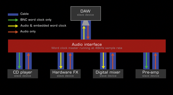
Caption - A typical network
First, let's consider a simple system in which an audio interface is connected to a DAW with a fast USB connection. The audio interface has both analogue to digital and digital to analogue converters. Incoming analogue signals are digitised and passed into the DAW where they are recorded, edited and processed. Signals which have already been recorded, and those produced by plug-ins, are sent back to the interface, usually in the form of a stereo master monitor mix where they are converted back to analogue to be sent to the monitors.
The DAW and the interface are closely integrated and can be considered as one system. Although the DAW is in effect a slave device, and the interface is set as the clock master, with its clock regulating all the analogue to digital, DAW processing and digital to analogue conversion, there are no synchronisation issues to resolve. Everything works well.
Demonstration But what if we add a new external hardware effect processor to this simple system and decide to hook it up digitally. We connect the digital out of the interface to the processor and the digital out of the processor back to the interface. Typically this would use a Toslink, SPDIF or AES3 connection. Now there are 2 types of signal that must be exchanged between the devices, the audio signal and a clock synchronisation signal.
Caption - Clock masters and slaves
Demonstration In this situation it would be sensible to leave the audio interface as the clock master and to set the processor as a clock slave, synchronising to the clock master. To achieve this you must make 3 settings on the effect processor ..
- Ensure it's sample rate is set to the same sample rate as the interface
- Set it to clock slave, or digital clock mode
- Select an incoming clock signal - BNC or embedded
Caption - Embedded and BNC word clock signals
Work clock is a timing signal passed between devices on a digital audio network. It is a square wave at the same frequency as the sample rate.
Word clock signals can be transmitted in 2 ways ..
- Via a separate word clock connection using a word clock lead which terminates with BNC connectors.
- Embedded in an SPDIF, AES, Toslink or ADAT signal - in this case the word clock, or 'bit clock' as it is known, runs in parallel to, and at the sample rate, of the audio signal.
Demonstration continued Because there is no advantage in using a BNC word clock connection, and our effect processor and audio interface may not have them, we can safely choose the embedded work clock option.
Caption - Why use a BNC word clock connection?
Contrary to popular belief, distributing work clock signals separately via separate BNC connectors does not produce superior synchronisation. Fortunately, project and home studio owners rarely need to use them. Also, many cost effective devices don't have BNC connectors.
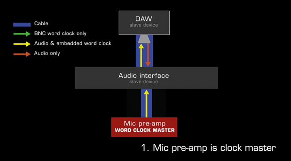
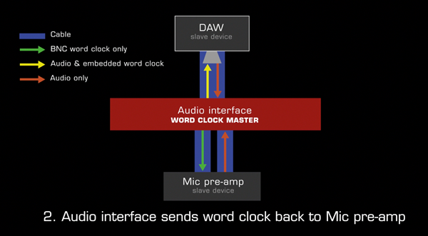
However, when you have a one way digital connection from a source device, such as a mic pre-amp channel with its own built-in analogue to digital converter, to an audio interface, and the interface is the clock master, the mic pre-amp has no way to synchronise to the system. There are 2 solutions ..
- Set the pre-amp channel as the clock master
- If your interface and pre-amp channel have BNC connectors, send word clock from the interface to the pre-amp channel
Caption - Daisy chained BNC word clock connections and termination
BNC connected devices can be daisy chained, but the last device in the chain may need to be terminated to prevent the word clock signal 'reflecting' back down the lead. This is usually accomplished either with ..
- a termination switch on the device
- hard wired termination in the device
- a BNC T piece which allows connection of a BNC 75 ohm termination plug
There is a relationship between cable length and signal strength that determines whether a signal should be terminated. A device's manual should idicate which, if any, type of termination is required, but if it doesn't, it should be possible to try different options and see which allow the device to lock without audible problems.
Caption - Correcting jitter and drift
At this point we should pause and consider the problem of lead induced jitter. If we are passing a clock signal down a lead, will it not be vulnerable to jitter also? The answer is yes! A master clock device cannot stop jitter developing in a lead, or other device, as it travels round a network. So we now have the problem of both the audio signal and word clock signal being affected by jitter!
We are now in danger of straying too deeply into digital theory, so it may be helpful for us to think of this problem like this ..
- Drift may be solved by distributing word clock synchronisation signals (ether embedded or BNC) from a master clock device to slaves. This ensures the devices are roughly clocked together.
- Jitter can be corrected partly be individual devices 're-timing' the samples using their own jitter correction electronics. Many manufactures advertise these features in their sales literature.
Because jitter and drift only becomes an audible problem when digital signals are converted back to analogue, it makes sense that the final correcting of these problems is handled by the master clock device, and that this device is itself the point at which signals enter and exit the central recording and mixing device, ie the DAW. It is therefore understandable that many believe that not only should your audio interface contain excellent converters and an accurate clock, but also jitter and drift elimination circuitry, a process sometimes known as "clock recovery".
Caption - To sum up
- unless you are using a digital mixer as the centre of your network, set your audio interface as the word clock master
- if you need digital audio connection, buy an audio interface with digital i/o connectors that match your other devices, and a BNC word clock output
- regardless of price, most audio interfaces have excellent converters, but not all have good jitter and drift elimination circuitry
- use embedded word clock where possible
- use BNC word clock only when necessary
Caption - Thanks for watching
The script for this video, with accompanying images, can be found at projectstudiohandbook.com
We suggest you subscribe at our YouTube channel, and join our mailing list at our website to receive notification of new videos, blog posts and subscriber only extras.
Thanks for watching.